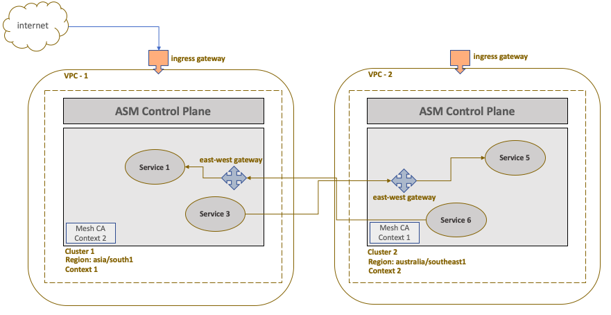
In this section. we will illustrate the Anthos service mesh communication using different VPC network. The use case will focus on setting up two GKE cluster with ASM installed in two different VPCs. As the clusters are in different networks, the services in a mesh will communicate with each other via internal east-west ingress gateway. The communication will happen over the Internet.
The mesh topology will look like the following:
Prerequisites
- You have already setup a Google project with two VPCs in separate regions. You can opt for any available two regions to implement this use case. For our setup, we will take Mumbai as one region and Singapore as another.
- You have Anthos GKE cluster setup in both the regions along with ASM version 1.8.3 installed. To understand how to install ASM, please follow the link to our website to get the latest installation steps – https://cloudsolutions.academy/solution/how-to-install-anthos-service-mesh-on-gke/. You will also have to install istio operator that will represent ingress gateway to serve the east-west traffic across two clusters. See section Set up east-west gateway below.
- The ASM Certificate Authority (CA) used will be Mesh CA (only available for GKE clusters). You could also use Citadel CA as an alternate option.
Set the cluster context
As a first step, identify the context of each cluster. The below command will lists the different cluster context.
kubectl config get-contexts -o name
gke_sandbox-111111_asia_south1-a_cluster-1

gke_sandbox-111111_asia_southeast1-a_cluster-2
The cluster context name follows a pattern: project-id_cluster-location_cluster_name. Assign the context name to $ctx1 and $ctx2 environment variables, each representing cluster one and two respectively.
export ctx1=gke_sandbox-111111_asia_south1-a_cluster-1

export ctx2=gke_sandbox-111111_asia_southeast1-a_cluster-2

Setup endpoint discovery between clusters
In this step you will enable each cluster to discover service endpoints of their counterpart, so that cluster one will discover service endpoints of the second cluster and vice versa.
istioctl x create-remote-secret --context=$ctx1 --name=cluster-1 | \

kubectl apply -f - --context=$ctx2

istioctl x create-remote-secret --context=$ctx2 --name=cluster-2 | \

kubectl apply -f - —context=$ctx1
You enable this by creating secrets for each cluster that grants access to kube API server of that cluster. Each secret is the certificate derived from the common root CA, in this case Mesh CA. You then apply the secret to the other cluster. In that way secrets are exchanged and the clusters are able to see the service endpoints of each other. In this case, the endpoint of ingress gateway that will serve the east-west traffic will be discovered.
Set up east-west gateway
Before installing ASM, create an istio operator config file in both the clusters which will set up an ingress gateway for east-west traffic (cross-cluster). The Mumbai cluster will represent west side of the traffic while the Singapore cluster will represent east side of the traffic. The config file for the Mumbai cluster will look like the following:
apiVersion: install.istio.io/v1alpha1

 kind: IstioOperator

 spec:

   values:

     global:

       meshID: mesh1

       multiCluster:

         clusterName: cluster-1

       network: vpc-1

   components:

     ingressGateways:

       - name: istio-eastwestgateway

         label:

           istio: eastwestgateway

           app: istio-eastwestgateway

           topology.istio.io/network: vpc-1

         enabled: true

         k8s:

           env:

             - name: ISTIO_META_ROUTER_MODE

               value: "sni-dnat"

             - name: ISTIO_META_REQUESTED_NETWORK_VIEW

               value: vpc-1

           service:

             ports:

               - name: status-port

                 port: 15021

                 targetPort: 15021

               - name: tls

                 port: 15443

                 targetPort: 15443

               - name: tls-istiod

                 port: 15012

                 targetPort: 15012

               - name: tls-webhook

                 port: 15017

                 targetPort: 15017
You can apply the above configuration as an overlay file while installing ASM using the -f flag.
istioctl install --context=$ctx1 -f istio-ingress-eastwest.yaml
Important thing to note is the port 15443 which is used for cross cluster communication. In order to expose this port for mesh services to communicate, you will have to create a custom gateway that will use Service Name Indication (SNI) routing with TLS extension on this port. The below code depicts the custom gateway that will actually facilitate east-west routing.
apiVersion: networking.istio.io/v1alpha3

 kind: Gateway

 metadata:

   name: multi-network

   namespace: istio-system

 spec:

   selector:

     istio: eastwestgateway

   servers:

     - port:

         number: 15443

         name: tls

         protocol: TLS

       tls:

         mode: AUTO_PASSTHROUGH

       hosts:

         - "*.local"
The above gateway named multi-network exposes port 15443 using SNI (with TLS extension) based routing allowing Kubernetes services with .local domain to communicate with Mumbai cluster mesh via this gateway. The TLS mode used is AUTO_PASSTHROUGH. This will, in effect, not terminate the TLS connection at the gateway and instead pass on the request to the target backend service. This mode also assumes that the client or the service from the calling cluster has initiated a TLS handshake. So if the service from the Singapore cluster uses plain vanilla http:// and not https://, the gateway will still pass through the request. This can create security loophole if the target backend does not handle TLS termination. We have kept it simple, as the purpose of this use case is to simply demonstrate cross cluster communication between two VPCs.
Apply both the above config file in the Singapore cluster (just change the name of the network) and you should be all set.
To test out the service to service communication across cluster, deploy a sample application and carryout the testing as described in Implement Multi cluster service mesh in a single VPC network section. Follow the steps from Setup the sample microservices application for testing section.
This completes the configuration and setup for Multi Cluster ASM setup across VPC.